I’ve detailed my Arduino photogrammetry setup, first here when it just used my phone, then here when I cludged together a physical trigger in the form of a servo motor.
That worked really well, and I’ve made a bunch of models with it that have come out absolutely superb.
However, to get the servo motor attached to the camera securely, it needed a lot of bluetac and elastic bands, and couldn’t easily be fitted and removed. It also had a tendancy to sometimes not press the trigger hard enough.
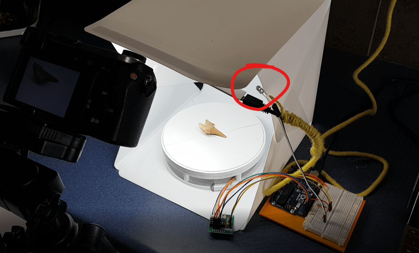
So, I’ve fixed that now, with the use of an infraRed LED. I bought these on Amazon for £5.99.
My previous Arduino code did include what I thought was a library that would control my camera, but it seemed that was not to be – when I looked at the GitHub page for the library, it was 10 years since it was last updated, so that’s maybe not a surprise.
After some Bing searching, I found this page which has the IR signal code for Sony nex cameras. I copied that across into my code, and behold!

Not only is this considerably less faffy, with having wires going from the breadboard to the camera, but it also means my camera doesn’t have the trigger blocked by a servo motor and I can use it normally again!
I also took the opportunity to re-work the timings between activating the turntable servo motor, firing the LED, and communicating with the phone, so everything works a bit more smoothly, and the pause between photos is long when the turntable needs to turn far, and short when it’s moving in small increments.
All the updated code is available on my github page: https://github.com/pfalkingham/AA-Scan

Thank you kindly for sharing. I am now building the same project. I was hoping you could provide the wiring diagram. I’m specifically interested in the IR Trigger. I have the turntable working :), just need to add my IR Diode
Not actually sure how to make a wiring diagram, but I can provide photos! Download them here: https://1drv.ms/u/s!Am5GkbZS_98XtaRu6u-01WUB7iuedw?e=9podJs
Thank you kindly 🙂