
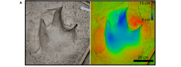
When documenting 3D models of tracks and other semi-planar fossils (or any object for that matter), one of the most useful ways of presenting the data is as a 3D height map.
We discussed this in the ‘standard protocol’ for documenting tracks paper, published in Palaeontology in 2018:
Despite much of my previous work being in Maya, I’ve been branching out and teaching myself Blender recently. It’s faster and the interface is nicer, though I’m still firmly embedded in Maya for the time being. I am using it as an excuse to render images in Blender though.
In Maya, I had a buggy Arnold shader network for applying height ramps. I thought I’d have a crack at learning the node-based shader system in Blender. Turns out, it’s super straight forward, and despite having never used it before, in less than an hour I had a height map shader that can flexibly be adjusted in scale and position!

This is what the shade node network looks like (click to view larger):

I’ll run you through it:
We start with a geometry node, from which we take the xyz position vector.
That goes into a ‘separate XYZ’ node where we extract Z (the vertical dimension in my scene – you could take whichever dimension you want the ramp to work on).
I then use a value node I’ve named distance combined with a math node to divide the XYZ position. This is driven by a custom scene property (we’ll come back to those later) and determines the distance in meters that the colour scale covers. Because the colour scale naturally scales from 0 to 1 m, if we divide the values we determine a 0 to whatever range. So if this number is 2, the scale will go from 0 to 2. If this value is 0.5 the scale goes from 0 to 50 cm.
I then repeat this process using another value node (named ‘offset’) and a math node which subtracts, so that the scale is moved by this driven value.
The output of that last math node goes into a colour ramp which is set blue-green-red at equidistant points (you might prefer a different colour scale, e.g. red-white-blue, which is better for accessibility, particularly for colourblindness).
That then goes into a standard Principled BSDF shader, which goes to the material output. You could just use a diffuse shader here, but I like being able to tweak specular, roughness, etc.
Now, those driven values. For those I’ve created two custom scene properties:
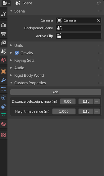
I just clicked the add button, edited the values to give them names (and set min/max values for the slider). If you set height map range to a negative value, you’re able to flip the colour scheme (so in this case red would be deeper, rather than blue).
The best part of this is it’s really easy to read off real values of the scale your height map is showing.
And that’s that. Here it is in action:

Will have to try this one day. Looks nicer than CloudCompare!
Exactly! I’ve used cloud compare myself a lot, and it’s fine, but being able to do it so easily in Blender where I can do other modelling stuff, and render with GPU, custom lighting etc is a big plus.