
I’ve previously discussed on this blog my love of dealing with a combination of rotation maths and awkward software.
I finally solved the problems that have been bugging my simulation workflow for the past 5 years, and I thought now would be a good time to share the mistakes I’ve made, and the code that works.
The problem:
During my time at Brown University, working with Stephen Gatesy, I collected a fair bit of data of Guineafowl walking over soft substrates using biplanar X-ray – the XROMM workflow.
The results of this data are beautiful:
We were interested in footprint formation, and that meant understanding just how the substrate was responding to the foot. The key attribute of XROMM was that we were able to see the toes and foot moving beneath the surface of the substrate. But the substrate itself is another matter.
To solve that problem, we used LIGGGHTS, a discrete element analysis software that let us simulate the individual sediment particles.
Now, the main gist of this is that our motion data exists in Maya, described as XYZ Euler rotations (with an XYZ rotation order). But LIGGGHTS requires rotations to be defined as axis-angle; that is, a single axis about which the object rotates, and the amount it rotates about that axis (expressed as the time required for 1 revolution). I’m still not entirely convinced I understand how axis-angle and the related quaternions work, but the best explanation I’ve seen is that it requires thinking in 4 dimensional space (think about how two points on the surface of a sphere can be expressed as different from each other either as a 2D vector that curves around the sphere, or in 3D space).
Converting from one to the other was not easy.
Failed ‘solutions’
Obviously I managed to cobble something together that worked fairly early on – we did publish on this after all. But it was a bit of a fudge (my code, not the science!): it involved calculating the X, Y, and Z rotations separately and passing them to LIGGGHTS as individual rotation commands in the same order as Maya’s rotation order (in this case X, Y, and Z). Liggghts would then implement each rotation ‘on top’ of the other, such that the point of rotation of the second rotation, rotated with the object as it rotated about the first rotation (see why this is hard?). The hardest part, was that to maintain long-axis rotation I had to manually calculate the third axis of rotation for each frame based on the cross product of the first two axes. Otherwise, when an object was vertical, the axes would start interfering with each other (essentially gimbal lock). In the end, for various reasons I just ended up knocking out long axis rotation all together. Most of the early work (and most of the current work for that matter) involved representing the foot as a series of cylinders, so it didn’t matter too much to the simulation if there was a bit of uncontrolled long-axis rotation.
I started out by exporting XYZ rotations and translations for each bone from maya, and then processing them in Matlab. I’m familiar with matlab, so this seemed the obvious direction to go in.
Here’s a snippet from that old script:
%% Calculate Translation Data
for i=2:noFrames(1)
    for j=1:noBones(1)
        %transmlations(frame, x/y/z, bone)
        translations(i,1,j) = AllJointsm(i,Proximal(j)*3-2) - AllJointsm(i-1,Proximal(j)*3-2);
        translations(i,2,j) = AllJointsm(i,Proximal(j)*3-1) - AllJointsm(i-1,Proximal(j)*3-1);
        translations(i,3,j) = AllJointsm(i,Proximal(j)*3) - AllJointsm(i-1,Proximal(j)*3);

        currentLocation(i,1,j) = currentLocation(i-1,1,j) + translations(i,1,j);
        currentLocation(i,2,j) = currentLocation(i-1,2,j) + translations(i,2,j);
        currentLocation(i,3,j) = currentLocation(i-1,3,j) + translations(i,3,j);
    end
end

%% Calculate Rotation data
for i=2:noFrames(1)
    for j=1:noBones(1)
        h = AllJoints(i,Proximal(j)*3+2)-AllJoints(i-1,Proximal(j)*3+2);
        a = AllJoints(i,Proximal(j)*3+3)-AllJoints(i-1,Proximal(j)*3+3);
        b = AllJoints(i,Proximal(j)*3+1)-AllJoints(i,Proximal(j)*3+1);

        c1 = cosd(h/2);
        c2 = cosd(a/2);
        c3 = cosd(b/2);
        s1 = sind(h/2);
        s2 = sind(a/2);
        s3 = sind(b/2);

        c1c2 = c1*c2;
        s1s2 = s1*s2;
        w = c1c2*c3 - s1s2*s3;
        xq = c1c2*s3 + s1s2*c3;
        yq = s1*c2*c3 + c1*s2*s3;
        zq = c1*s2*c3 - s1*c2*s3;

        outputRotationData(i,1,j) = 2*acosd(w);
        if(outputRotationData(i,1,j) ~= 0)
            outputRotationData(i,2,j) = xq;
            outputRotationData(i,3,j) = yq;
            outputRotationData(i,4,j) = zq;
        else
            outputRotationData(i,2,j) = 0;
            outputRotationData(i,3,j) = 0;
            outputRotationData(i,4,j) = 1;
        end
        norma = sqrt(outputRotationData(i,2,j)*outputRotationData(i,2,j)+outputRotationData(i,3,j)*outputRotationData(i,3,j)+outputRotationData(i,4,j)*outputRotationData(i,4,j));
        outputRotationData(i,2,j) = outputRotationData(i,2,j)/norma;
        outputRotationData(i,3,j) = outputRotationData(i,3,j)/norma;
        outputRotationData(i,4,j) = outputRotationData(i,4,j)/norma;
    end
end

%% output data to file

fileIDoutput = fopen('transRotData', 'a');

for i=2:noFrames(1)
    for j=1:noBones(1)
        if(outputRotationData(i,1,j) ~= 0 & outputRotationData(i,2,j)+outputRotationData(i,1,j)+outputRotationData(i,3,j) ~= 0)  %%DOUBLE CHECK THIS, * SHOULD BE + I THINK.
            fprintf(fileIDoutput, 'fix rotate%s%i all move/mesh mesh %s rotate origin %e %e %e axis %e %e %e period %f\n', bone{j}, i, bone{j}, currentLocation(i-1,1,j), currentLocation(i-1,2,j), currentLocation(i-1,3,j), outputRotationData(i,2,j), outputRotationData(i,3,j), outputRotationData(i,4,j), ((360)/outputRotationData(i,1,j))*(1/framerate));
        else
            %may need dummy line
        end
    end
    for j = 1:noBones(1)
        fprintf(fileIDoutput, 'fix move%s%i all move/mesh mesh %s linear %e %e %e\n', bone{j}, i, bone{j}, translations(i,1,j)*framerate, translations(i,2,j)*framerate, translations(i,3,j)*framerate);
    end
    fprintf(fileIDoutput,'run %i\n', frame_ts);
    for j = 1:noBones(1)
        fprintf(fileIDoutput, 'unfix move%s%i\n', bone{j}, i);
    end
    for j = 1:noBones(1)
        if(outputRotationData(i,1,j) ~= 0 & outputRotationData(i,2,j)+outputRotationData(i,1,j)+outputRotationData(i,3,j) ~= 0) %%DOUBLE CHECK THIS, * SHOULD BE + I THINK.
            fprintf(fileIDoutput, 'unfix rotate%s%i\n', bone{j}, i);
        end
    end
end
%% output the initial setupdata
Getting ahead of myself.
A big problem for me through this time was that testing I had everything right was a royal pain in the backside. It meant firing up my test scenario in Maya (a cylinder rotating in interesting ways that included long axis rotation), exporting data, opening MATLAB, running the MATLAB script, then running LIGGGHTS, then opening Ovito and visualizing the results. Debugging was a nightmare because each run took several minutes, even in this most simple of test cases, and inserting only a single particle for the discrete element simulation.
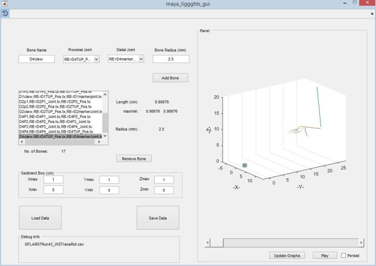
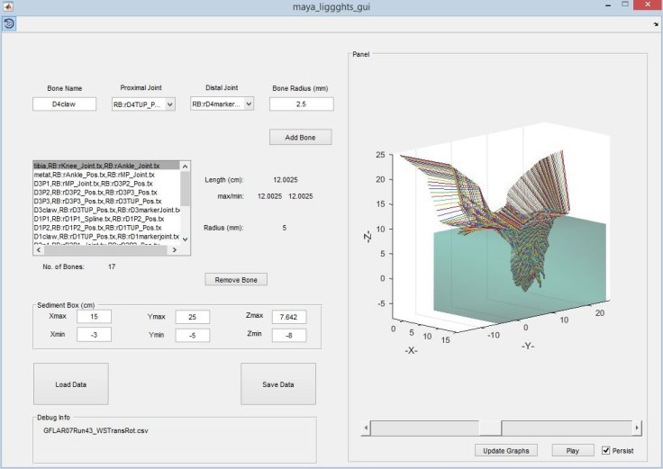
So, I embarked upon an endeavour to write the whole thing in MATLAB. I would export the XYZ rotations and translations from Maya as a plain text file, read it in, then visualize the rotations in 3D in MATLAB. It would then calculate the ‘bones’ as the vectors between two joints. Having checked everything worked, I could press a button and it would generate STL files of cylinders at the correct sizes, as well as the input scripts for LIGGGHTS.
Honestly, it was beautiful:
Alas, ultimately I had less control over what size bones could be (in terms of cylinder diameter), and I was locked into using cylinders forever. It also didn’t solve the missing long-axis rotation problem, because ultimately it was still using the same code as before. And worst of all, it was another piece of software in my workflow.
So, I set out to try and transfer as much as I could over a native Maya script, so I could generate cylinders and export LIGGGHTS input files directly from within Maya, able to visualize the motion of said bones and cylinders. I cobbled some scripts together that would measure distances between bones and then create cylinders accordingly, which it could output as STL.
Here’s a snippet from my Maya-LIGGGHTS script as it was in 2016, to show you what the conversion process from X,Y,Z rotations to Axis-angle looked like (written in MEL, the maya scripting language):
   for ($item in $bones)
    {
    string $buffer[];
    tokenize $item ":" $buffer;
    string $cleanName = $buffer[size($buffer)-1];

        //Get current x, y, z, rotation + translation
        currentTime $i;
        $currX = getAttr ($item+".translateX");
        $currY = getAttr ($item+".translateY");
        $currZ = getAttr ($item+".translateZ");
        $currRX = getAttr ($item+".rotateX");
        $currRY = getAttr ($item+".rotateY");
        $currRZ = getAttr ($item+".rotateZ");

        //Get previous xyz rot + trans
        currentTime ($i-1);
        $prevX = `getAttr ($item+".translateX")`;
        $prevY = `getAttr ($item+".translateY")`;
        $prevZ = `getAttr ($item+".translateZ")`;
        $prevRX = `getAttr  ($item+".rotateX")`;
        $prevRY = `getAttr ($item+".rotateY")`;
        $prevRZ = `getAttr ($item+".rotateZ")`;

        //Command Translation
        fprint $fileId2 ("fix    move"+$cleanName+$i+" all move/mesh mesh "+$cleanName+" linear "+($currX-$prevX)*$frame_rate+" "+($currY-$prevY)*$frame_rate+" "+($currZ-$prevZ)*$frame_rate+"\n");

        //calculate rotation since last frame:
        float $diffRX = $currRX - $prevRX;
        float $diffRY = $currRY - $prevRY;
        float $diffRZ = $currRZ - $prevRZ;

        //New rotation calculation based on matrix from xform -q -m <mesh>
        float $deargodno[] = `xform -q -m $item`;

        //Calculate y as cross product of x and z (z being 0 0 1) - based on http://www.mathsisfun.com/algebra/vectors-cross-product.html
        float $cx = ($deargodno[2]*0) - ($deargodno[1]*1);
        float $cy = ($deargodno[0]*1) - ($deargodno[2]*0);
        float $cz = ($deargodno[1]*0) - ($deargodno[0]*0);

        //do x
        if ($diffRX != 0)
        {
            float $periodX = (360/$diffRX) * (1/$frame_rate);
            fprint $fileId2 ("fix    rotatex"+$cleanName +$i+" all move/mesh mesh "+$cleanName+" rotate origin "+$prevX+" "+$prevY+" "+$prevZ+" axis "+$deargodno[0]+" "+$deargodno[1]+" "+$deargodno[2]+" period "+$periodX+"\n");
        }
        //do y
        if ($diffRY != 0)
        {
            float $periodY = (360/$diffRY) * (1/$frame_rate);
            fprint $fileId2 ("fix    rotatey"+$cleanName+$i+" all move/mesh mesh "+$cleanName+" rotate origin "+$prevX+" "+$prevY+" "+$prevZ+" axis "+$cx+" "+$cy+" "+$cz+" period "+$periodY+"\n");
        }
        //do Z
        if ($diffRZ != 0)
        {
            float $periodZ = (360/$diffRZ) * (1/$frame_rate);
            fprint $fileId2 ("fix    rotatez"+$cleanName+$i+" all move/mesh mesh "+$cleanName+" rotate origin "+$prevX+" "+$prevY+" "+$prevZ+" axis 0 0 1 period "+$periodZ+"\n");
        }
    }
    fprint $fileId2 ("run "+$timesteps_per_frame+"\n");
You may notice the variable ‘deargodno’ used to get information from the xfrom matrix in Maya. That’s because I didn’t really have a good grasp of what was coming out of there and was hoping for the best a little bit. I added that variable with some trepidation then never changed the name. Anyway, it did the job, so that was good. It had a fairly delicate and intricate workflow though:, and the slightest mislabelling of an item in the Maya scene would cause it to crash out, leaving the connection to the file open, and meaning Maya needed restarting (which isn’t a quick process).
I finally had a workflow that worked (as a workflow is meant to do). But occasionally I’d still come up against problems – usually when a bone rotated in such a way that the long axis and another axis aligned. But also at other times for no reason I could fathom. I initially hoped that running the Euler filter in maya would solve these problems, and sometimes it did. Hence why I got so excited a while back. Here’s a gif of semi-success:
But sometimes it didn’t work, and bones would start rotating in ways I could not fathom, and that unknown just made things worse.
Breaking point
This worked ‘well enough’ for quite some time until two things happened earlier this year:
1) LIGGGHTS v3.7 temporarily broke the ability to stack rotations in a sensible way, meaning my fudge of applying 3 rotations separately (and not really controlling long-axis rotation) would no longer work – Disaster!
2) We reached a point in our research where we were interested in whether the detailed shape of the foot would have any real effect on the resulting track morphology. This of course meant that my current cylinder implementation was insufficient, and actually got in the way.
I knew that somehow, Quaternions held the solution (Steve Gatesy often commented quaternions would be the solution, to the point that it was something of a running joke in the Gatesy Lab during 2013):

I’d dipped into looking at quaternions on occasion in the past, but very quickly shied away from it because quaternions are really hard. But now everything was falling apart, I knew I had to get something that would cover long-axis rotations properly, once and for all, and that could be easily converted to a single axis-angle command in my liggghts input file.
I tried for a long time to convert between Euler angles and axis-angle/quaternions. I spent a lot of time on http://www.euclideanspace.com/maths/geometry/rotations/ and am eternally grateful to that site for it’s fantastic, well explained information.
But it didn’t quite get me there. The fundamental problem was that the issues were arising in the very existence of Euler angles in the first place, from which I was trying to convert.
Now, Maya actually works in Quaternions behind the scenes, but getting access to that isn’t intuitive (until you know how). Steve finally made the breakthrough discovering a snippet of code online that referred to accessing the quaternions via python. From there, it was a week or two of trial and error (and some more error) before I finally managed to get this together:
for ($item in $bones)
    {
    string $buffer[];
    tokenize $item ":" $buffer;
    string $cleanName = $buffer[size($buffer)-1];
    string $nodeString = "node = pm.PyNode('" + $item + "')";
    python($nodeString);

        //Get current x, y, z, translation
        currentTime ($i-1);
        $currX = `getAttr -t $i ($item+".translateX")`;
        $currY = `getAttr -t $i ($item+".translateY")`;
        $currZ = `getAttr -t $i ($item+".translateZ")`;
        //Get previous xyz trans
        $prevX = `getAttr ($item+".translateX")`;
        $prevY = `getAttr ($item+".translateY")`;
        $prevZ = `getAttr ($item+".translateZ")`;

        //Command Translation
        fprint $fileId2 ("fix    move"+$cleanName+$i+" all move/mesh mesh "+$cleanName+" linear "+($currX-$prevX)*$frame_rate+" "+($currY-$prevY)*$frame_rate+" "+($currZ-$prevZ)*$frame_rate+"\n");

        // get quat directly
        python("quat1 = node.getRotation(quaternion=True)");
        currentTime($i);
        python("quat2 = node.getRotation(quaternion=True)");
        //calculate difference between frames:
        python("quat3 = quat1.inverse() * quat2");

        python("aaxis = om.MVector()");
        python("angUtil = om.MScriptUtil()");
        python("angUtil.createFromDouble(0)");
        python("angDoub = angUtil.asDoublePtr()");
        python("quat3.getAxisAngle(aaxis,  angDoub)");
        python("theta =  om.MScriptUtil.getDouble(angDoub)");

        $axisX = python("aaxis[0]");//MAY NEED TO NORMALIZE AXIS!  - nope, probably not due to liggghts using period.
        $axisY = python("aaxis[1]");
        $axisZ = python("aaxis[2]");
        $aangle = python("math.degrees(theta)");  //doing the math in python while variable is there.

       //print axis and period:
        if ($aangle != 0)
        {
            float $period = (360/$aangle) * (1/$frame_rate);          //calculate period from angle
            fprint $fileId2 ("fix    rotate"+$cleanName +$i+" all move/mesh mesh "+$cleanName+" rotate origin "+$prevX+" "+$prevY+" "+$prevZ+" axis "+$axisX+" "+$axisY+" "+$axisZ+" period "+$period+"\n");
        }
    }
It gets a bit messey with Python calls (I was trying to stay in Mel as much as possible), but the real clincher was that the python/Maya API could get quaternions and convert them directly into axis-angle representation! (The minor hold up here was in getting per-frame rotations; turns out you can’t just subtract quaternions, you have to multiply one by the inverse of the other… obviously?).
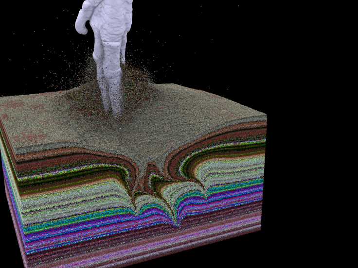
Anyway, the result is that now I have a working script that is robust, captures all the motion, and can be applied to complex geometry, not just cylinders:
I plan to make the Maya->LIGGGHTS MEL scripts available in the medium term (once I’ve got the documentation down), which would hopefully be useful for people working in LIGGGHTS (with anything – machinery, industry, not necessarily dinosaur footprints).

I was just wondering… What if someone could properly animate the mechanics of the leg movement in an animation software (like Maya, 3dS Max or Blender), and use the animated leg in a particle simulation in the proper software, or a software like X-Particles, or even in Unreal Engine 4. Particle simulations in animation and game development software is quite powerful and some really include physical properties of the interacting particles. At the moment I can imagine that they have the advantage of allowing real-time interaction between the 3D model and the particles – giving more freedom to explore movements in a “virtual experiment”, but would lack an output in terms of numbers that may be necessary for “valuable results” in a scientific context.
Sorry, I wrote a comment for this post just now, but I am not sure if it was posted properly, because I can’t see it here. I accidentally pressed the “back” button on my browser.
I will write it again here.
I was wondering what are your (and your colleagues, if possible) thoughts on the possibility of someone being able to properly create an animation of the leg mechanics using animation software (like Maya, 3dS Max or Blender), and performing a simulation in the particle simulation tools in these software (or even in Unreal Engine4). They usually have powerful particle simulations that include real physics (and some times they have their own add-ons that improve on the physics of the simulations.
I just imagine that from one side, they would be very helpful because they allow more direct control of all the elements, more freedom of mechanics and real-time interaction between the 3D model and the particles. That opens it up to a bunch of potential virtual experiments. It would also avoid these issues with having to jump between different software for manipulating parts of the data.
But on the other side, it does not wield a direct output in terms of values or numbers (if you wanted to calculate forces and things like that), which may render it less “scientific results” oriented. And there is the issue of the precision/accuracy of the simulations, since it is known that, for games and animations, even tho they are implementations of physics simulations, they are optimized for faster performance.
This is just something that I’ve been thinking for a while – what is the usefulness of physics based simulations implemented in animation software for scientific research. I know that so far, no one has ever done such comparison.
Hi Diego, yeah, comments will only appear once approved.
So your idea of using animation software for testing particle sims is something I’ve been toying with. I’ve been trying out Maya’s bifrost system for exactly this reason. However, there’s a couple of issues with even using it to approximate what’s happening before moving to a ‘proper’ physically accurate sim:
Firstly, it’s still quite slow and disk-space intensive to cache. Even just a few 10’s of thousands of particles takes a long time – more than would realistically be called ‘real time’. At very large particle numbers, the animation systems tend to grind a little. So it’s hard to run comparable test cases.
Secondly, parameters don’t correlate between the animation approximations and the Simulation parameters, which means even after exploring in animation, it’s difficult to translate that to Simulation without having to do all the parameter testing again.
That being said, I think the real money for research is in animation, rather than simulation, and it wouldn’t suprise me at all if in just a few years the Animation particle sims are perfectly useful for situations like this.
Here’s an early test I did with cone-penetration. You can see it works, but isn’t particularly ideal: https://youtu.be/EXR5JXU0ot0
True, true! The more parameters you add to particles simulations and the more particles you add, the slower it gets. And yeah, the gaming and animation industry are the ones driving the development of both hardware and software (thanks to gamers and animation fans!). Unfortunately, science will have to wait to benefit from the “bread crumbs” dropped by the industry. Maybe you should take a look at X-particles and Blender Molecular Add-on. But then again, if they are just for visualization, and not for the experiment itself, it may not be worth investing time on them now.
But it is good to know that there are scientists like you, who are open to the idea of exploring computer graphics and game development software as part of your scientific tool set. Seems like mechanical engineers are starting the explore these tools (https://www.researchgate.net/publication/308668585_Virtual_reality_and_vehicle_dynamics_in_unreal_engine_environment)